Palomar Airport Design
Flood Control Grant Project - McClellan-Palomar Airport Water Quality Basin: Project Design Elements
 The facility was designed to treat runoff for the
entire tributary watershed, assuming ultimate land use. This watershed
includes the majority of the runway, taxiways, and plane parking
areas. The total watershed tributary from the airport to the proposed
facility is 89.9 acres, comprised of nearly 100% impervious areas.
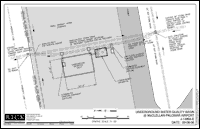
The combined treatment facility is comprised of a hydrodynamic separator (Vortechnics Model PC 1319) and a detention vault (StormTrap Precast Units). Treatment through the combined flow-based and volume-based facility placed in series provides a solution that exceeds the standard requirements for water quality treatment (per SUSMP numeric sizing criteria).
The proposed project collects the combined flows and conveys them through a diversion structure that directs low flows through the proposed facility. Larger flows that exceed the capacity of the facility are not diverted and continue downstream through the 36-inch main line reinforced concrete pipe (RCP) alignment.
The low flows exit the diversion structure and enter the hydrodynamic separator (HDS) where pollutants settle out as water travels through a collection of screens, baffles, weirs, and orifices until exiting the downstream end of the unit. At the downstream end of the HDS, a 30-inch RCP conveys these treated flows into the detention vault.
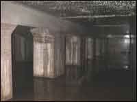
The detention vault provides a second opportunity for pollutants to settle as the water is detained for an extended period as a low-flow restrictor plate at the downstream end of the vault controls outflow.
In order for the proposed project to operate as designed, periodic inspections and maintenance will be required. It is currently anticipated that the HDS should be maintained 1-2 times per year and the detention vault once every one or two years. Each of these frequencies may increase and/or decrease, as site-specific conditions become evident.
Links to the final design report and construction plans are provided at the bottom of this page.
 |
 |
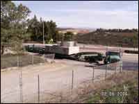
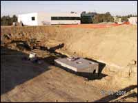
| Diversion Weir conveys low-flows towards Treatment Facilities | Hydrodynamic Separator Unit (bottom half) is delivered during construction |
 |  |
| Hydrodynamic Separator Unit installed and ready for storm drain connections | Detention Vault (as seen underground) |
[ Final Design Report ] [ As-Built Plans ]
[ Project Overview ] [ Project Design Elements ] [ Effectiveness Assessment ] [ Outreach ]


